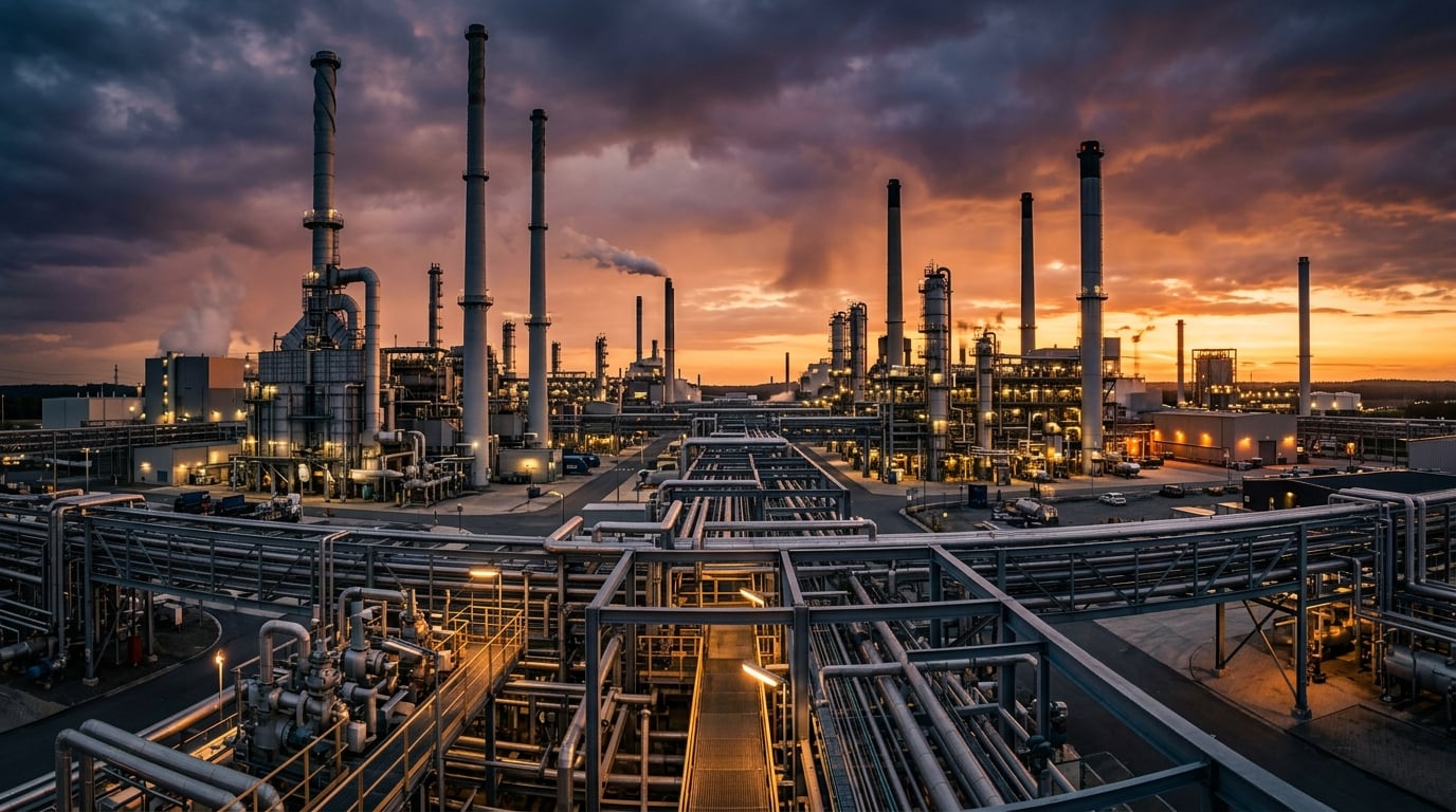
Convert Industrial Chimneys into Heat Recovery & Air Cleaning Systems
Bubble pipe (condensing scrubber) technology captures wasted thermal energy and removes pollutants from flue gases — turning a liability into an asset for foundries, steel plants and heavy industry.
How Bubble Pipe Technology Works
A bubble pipe system converts a conventional industrial chimney into a combined heat recovery and air cleaning unit. Instead of allowing hot, polluted flue gases to escape directly into the atmosphere, the system routes exhaust gases through a column of liquid (typically water or a chemical scrubbing solution). The gas is forced through the liquid as bubbles, creating extensive gas-liquid contact surface area. This process simultaneously transfers thermal energy from the hot gas to the liquid and captures particulates and gaseous pollutants through absorption, impaction, and diffusion mechanisms.
Direct-Contact Heat Exchange
Hot flue gas is bubbled directly through a liquid medium, enabling highly efficient heat transfer without the thermal resistance of a solid heat exchanger wall. Both sensible heat and latent heat (from water vapor condensation) are captured.
Condensing Scrubber Action
By cooling flue gas below its dew point (typically 45-65°C depending on fuel type), the system condenses water vapor from the exhaust, releasing over 2 GJ of latent heat per ton of condensed water. This latent heat recovery can increase overall system efficiency by 10-15%.
Multi-Mechanism Pollutant Capture
Pollutants are removed through three simultaneous mechanisms: impaction (particles >1 µm collide with liquid droplets), diffusion (sub-0.1 µm particles undergo Brownian motion into droplets), and chemical absorption (gaseous pollutants like SO₂ dissolve into the scrubbing liquid).
System Components
Bubble Column Reactor
Primary gas-liquid contacting vessel where flue gas is dispersed as bubbles through the scrubbing liquid
Gas Distribution Sparger
Perforated plate or nozzle array at the base of the column that creates uniform small bubbles for maximum gas-liquid contact area
Heat Recovery Exchanger
Secondary heat exchanger that transfers captured thermal energy from the scrubbing liquid to a useful heat sink (district heating, process water preheating, space heating)
Demister / Mist Eliminator
Prevents liquid carryover into the cleaned exhaust stream
Liquid Recirculation System
Pumps, tanks, and pH control system that manages the scrubbing liquid chemistry and flow rates
Induced Draft Fan
Maintains proper gas flow since the scrubbing process eliminates natural chimney draft (buoyancy)
Automated Control Unit
Monitors and adjusts pH, temperature, flow rates, and pressure differentials; includes bypass function for when heat store is full
The Process, Step by Step
From furnace to useful heat: follow the flue gas through the bubble column to heat recovery.
Hot flue gas (200-800°C depending on process) exits the industrial furnace or process
Pre-cooling stage reduces gas temperature to 150-200°C (optional, depending on initial temperature)
Gas enters the bubble column reactor through the sparger at the base
Gas rises as bubbles through the scrubbing liquid column (1-5 meters of liquid depth)
Heat transfer occurs: gas cools from 150-200°C to 40-60°C
Pollutants are captured in the liquid through absorption and impaction
Water vapor condenses as gas cools below dew point, releasing latent heat
Cleaned, cooled gas exits through demister and is released to atmosphere
Heated scrubbing liquid circulates through heat recovery exchanger
Recovered heat is delivered to useful applications (heating, process water, etc.)
Scrubbing liquid is treated, pH-adjusted, and recirculated
Heat Recovery Mechanisms & Efficiency
Direct gas-liquid contact captures both sensible and latent heat — including energy otherwise lost up the chimney.
Sensible Heat Recovery
40-60%Thermal energy captured by cooling the flue gas from its inlet temperature down to near ambient or liquid temperature. Proportional to the temperature difference and the specific heat capacity of the gas.
Latent Heat Recovery
40-60%Thermal energy released when water vapor in the flue gas condenses. This is only possible when the gas is cooled below its dew point. Yields approximately 2.26 GJ per ton of water condensed.
Applications for Recovered Heat
District Heating Networks
Ideal application with return water at 40-50°C enabling maximum latent heat recovery. Heat delivered at 13-32 USD/MWh vs. 38-59 USD/MWh for gas boilers.
Boiler Feed Water Preheating
Preheating combustion air or boiler feed water from 15°C to 60-80°C, reducing fuel consumption by 5-10%.
Process Water Heating
Supplying warm water for industrial cleaning, chemical processes, or material preparation.
Space Heating
Heating workshops, offices, and warehouses using recovered thermal energy via hydronic systems.
Thermal Energy Storage
Storing recovered heat in insulated tanks for use during peak demand periods or process downtime.
Air Cleaning & Purification Performance
Impaction, diffusion and chemical absorption remove particulates, acid gases and metals in a single wet stage.
Removal Efficiency by Pollutant
Advantages over Dry Systems
Simultaneous heat recovery and pollutant removal in a single unit
No risk of filter fires (unlike bag filters in high-temperature applications)
Effective for both gaseous and particulate pollutants simultaneously
Can handle high moisture and high temperature exhaust streams
Lower outlet gas temperature reduces visible plume (white steam) from chimney
Particulate Matter (PM₁₀)
90-99%Mechanism: Impaction with liquid droplets and bubble surfaces
Fine Particulates (PM₂.₅)
75-95%Mechanism: Combined impaction and diffusion in bubble column; enhanced with Venturi pre-stage
Sulfur Dioxide (SO₂)
95-99%Mechanism: Chemical absorption into alkaline scrubbing solution
Hydrochloric Acid (HCl)
95-99%Mechanism: Absorption into aqueous scrubbing liquid
Heavy Metals (Pb, Hg, Cd)
70-95%Mechanism: Particulate-bound metals captured via impaction; vapor-phase metals via chemical absorption
VOCs
50-90%Mechanism: Absorption and condensation; dependent on compound solubility
Nitrogen Oxides (NOₓ)
20-50%Mechanism: Limited absorption; NO is poorly soluble in water
Technical Specifications & Performance Data
Typical design parameters and performance data for custom-engineered systems.
| Parameter | Range |
|---|---|
Gas flow capacity Scalable through modular design; multiple columns in parallel | 170 – 297,000 m³/h |
Inlet gas temperature Pre-cooling stage required above 400°C | 150 – 800°C |
Outlet gas temperature Below dew point for latent heat recovery | 40 – 60°C |
Liquid-to-gas ratio Higher ratios improve removal efficiency | 0.5 – 3.0 L/m³ |
Pressure drop Compensated by induced draft fan | 500 – 2,500 Pa |
Liquid column depth Greater depth increases contact time | 1 – 5 m |
Residence time Minimum contact time for absorption | 1 – 5 s |
System energy consumption Offset significantly by recovered heat | < 1-3% of output |
Materials of Construction
Selected based on exhaust chemistry, temperature and structural requirements. FRP for acidic environments; stainless steel for high-temperature applications.
Cost-Benefit Analysis
CAPEX, operating costs and ROI: heat recovery turns compliance into profitability.
Capital Cost by System Size
Turnkey installed cost ranges in USD. A pre-engineering study ($16k–$54k) is recommended before final quotation.
Annual Operating Costs
Fan and pump power, reagents, water, waste disposal and maintenance labour. Total: $40,000 – $205,000 / year.
Cumulative Cash Position Over Time
Illustrative medium system (~$1.1M CAPEX). Heat-recovery savings and avoided fuel costs drive payback in 2–3 years.
Case Studies & Industry Examples
From foundries to steel plants and biomass power: real-world results of heat recovery and air cleaning.
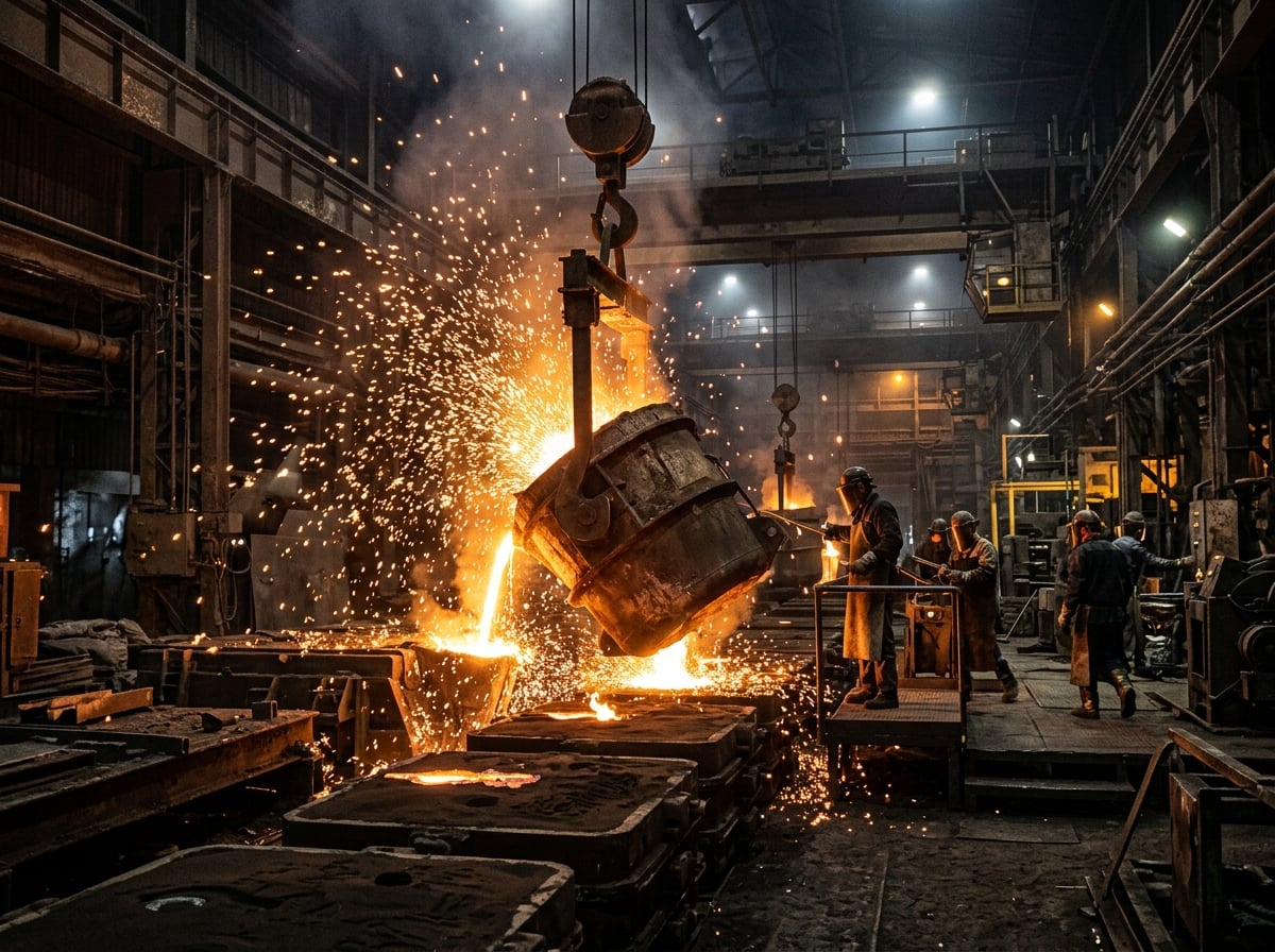
Iron Foundry VOC & Heat Recovery System
High levels of VOCs (BTEX) and particulate emissions from melting and casting processes. Regulatory pressure to reduce Hazardous Air Pollutants (HAPs).
Combined scrubber and Regenerative Thermal Oxidizer (RTO) system with integrated heat recovery. The wet scrubber removes particulates and acid gases; the RTO achieves 98.5% VOC destruction. Recovered RTO heat preheats incoming process air.
- 98.5% VOC destruction rate efficiency
- >95% particulate reduction
- Significant fuel savings via air preheating
- Full compliance with EPA HAPs standards
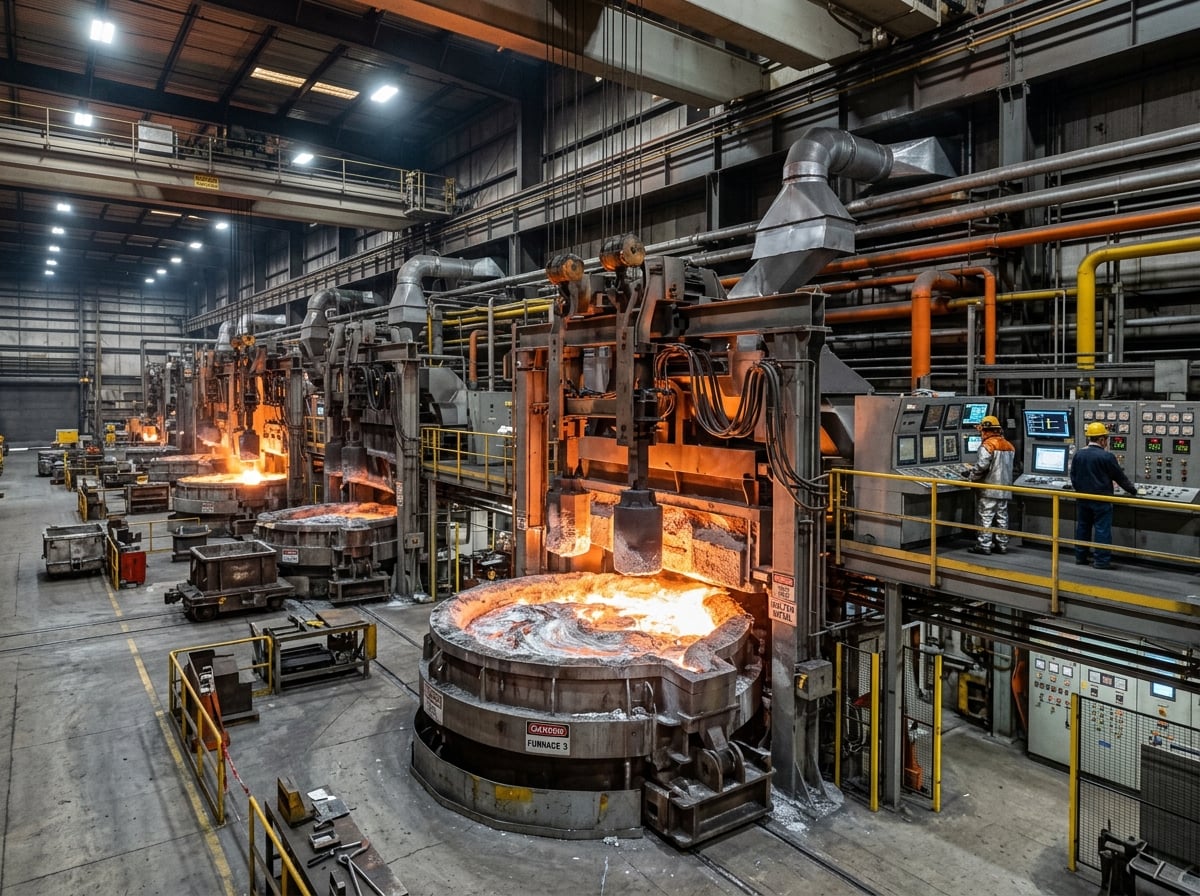
Aluminum Foundry Waste Heat Recovery
Melting consumes 40-60% of total energy; significant thermal energy lost through exhaust at 400-700°C. Need to reduce CO₂ footprint while maintaining production capacity.
Thermal power balance study followed by a condensing scrubber system with heat exchangers integrated into the exhaust duct. Recovered heat feeds facility heating and process water systems.
- Significant primary fuel reduction
- Verified facility CO₂ reduction
- Payback period under 3 years
- Improved surrounding air quality
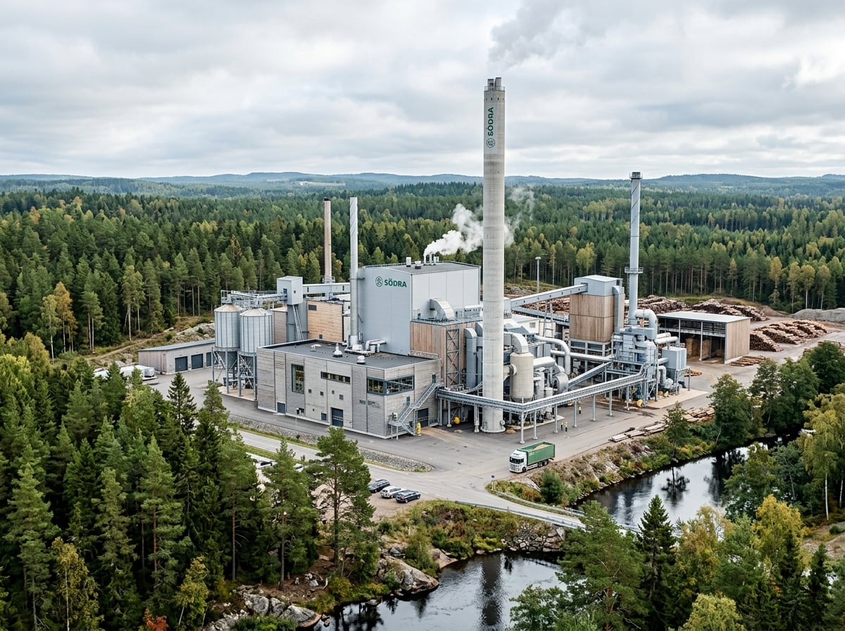
Biomass Power Plant Condensing Scrubber
Biomass combustion produces flue gas with high moisture content. Standard non-condensing systems waste significant latent heat. District heating network needs a supplemental low-cost heat source.
Wet flue gas cleaning and condensing heat recovery system. Flue gas is saturated, scrubbed and cooled below its dew point. Recovered latent and sensible heat feeds the district heating return line.
- 10-15% increase in overall plant efficiency
- Several MW added to district heating
- Significant PM and SO₂ reduction
- Heat delivered at 13-24 USD/MWh
Steel Plant Integrated Heat Recovery
Extremely high exhaust temperatures (700-1500°C) from metallurgical processes. Massive energy waste and high operating costs. Stringent new environmental regulations.
Multi-stage system: waste heat boiler for initial cooling (generating steam), evaporative cooling, then a condensing scrubber for final heat recovery and pollutant removal. Heat pump integration maximises low-temperature recovery.
- Heat recovery below $2.70-3.00 / GJ
- 20-50% reduction in primary energy waste
- Full compliance with national standards
- Positive return within 2-4 years
Carbon Filtration & Resource Recovery
An activated carbon bed in the scrubbing water captures residual metals and gases — turning chimney waste into recoverable resources.
Activated Carbon Bed Polishing Stage
A bed of activated carbon is integrated into the scrubbing liquid circuit as a final polishing stage. As the washed gas and recirculated water pass through the highly porous carbon (surface area 500–1,500 m²/g), the carbon adsorbs the trace pollutants that a water scrubber alone cannot fully capture — vapor-phase heavy metals, dioxins/furans, residual VOCs and odour compounds.
What Can Be Recovered
Beyond heat, the system converts captured pollutants into valuable material streams — a genuine circular economy.
Recovered Thermal Energy
Sensible + latent heat fed to district heating, process water or space heating.
Distilled Condensate Water
Clean condensed water treated and reused, cutting freshwater demand.
Heavy-Metal Concentrate
Metals captured on carbon & in sludge are sent to specialised refiners for recovery.
Metal-Oxide Dust
Recovered particulate can be recycled back into the smelting/foundry feed.
Gypsum / Sulphur Products
SO₂ + lime reaction yields gypsum for plasterboard & cement industries.
Regenerated Activated Carbon
Spent carbon is thermally regenerated or valorised for energy, closing the loop.
Environmental Benefits & Emission Reduction
Direct pollutant reduction and indirect CO₂ savings from avoided fuel — aligned with major regulatory frameworks.
Direct Emission Reductions
By recovering waste heat and displacing fossil fuel combustion for heating, the system indirectly reduces CO₂ emissions proportional to the avoided fuel consumption.
Particulate Matter
Dramatically improved local air quality; reduced respiratory health risks for workers and communities.
Sulfur Dioxide (SO₂)
Elimination of acid rain contribution; protection of ecosystems and infrastructure.
Heavy Metals
Reduced bioaccumulation in soil, water, and food chains.
VOCs / HAPs
Reduced ground-level ozone formation; decreased carcinogenic exposure.
Visible Plume Reduction
Cooling gases below dew point and removing moisture eliminates the visible white steam plume, improving community relations.
Water Recycling Potential
Condensed water from flue gas can be treated and reused in industrial processes, reducing freshwater consumption.
Noise Reduction
The liquid column acts as a natural sound dampener, reducing noise transmission through the chimney system.
Circular Economy
Captured SO₂ can be converted to marketable gypsum; captured CO₂ can be used for synthetic fuel or building materials.
Regulatory Alignment
Helps facilities comply with Best Available Techniques (BAT) requirements
Reduces carbon footprint, potentially lowering emission trading obligations
Meets or exceeds standards for Hazardous Air Pollutants
Aligns with multi-pollutant emission standards
Compliant with classified installations requirements
Applications Across Every Scale
Bubble pipe technology is modular — it scales from a small foundry workshop to a large integrated steel complex. Here is how the system adapts across every scale of operation.
Small-Scale Installations
Typical deployments
- Artisan foundries & small casting shops
- Bakeries & food-processing ovens
- Small biomass & wood-fired boilers
- Workshop and local heating loops
Medium-Scale Facilities
Typical deployments
- Mid-size iron & aluminum foundries
- Brick, ceramic & glass kilns
- District heating substations
- Chemical, paper & textile plants
Large Industrial Complexes
Typical deployments
- Integrated steel mills & smelters
- Large biomass & waste-to-energy plants
- Cement & lime production lines
- Municipal district heating networks